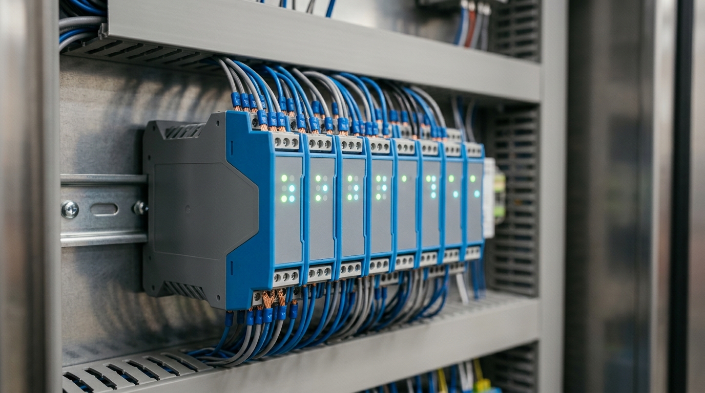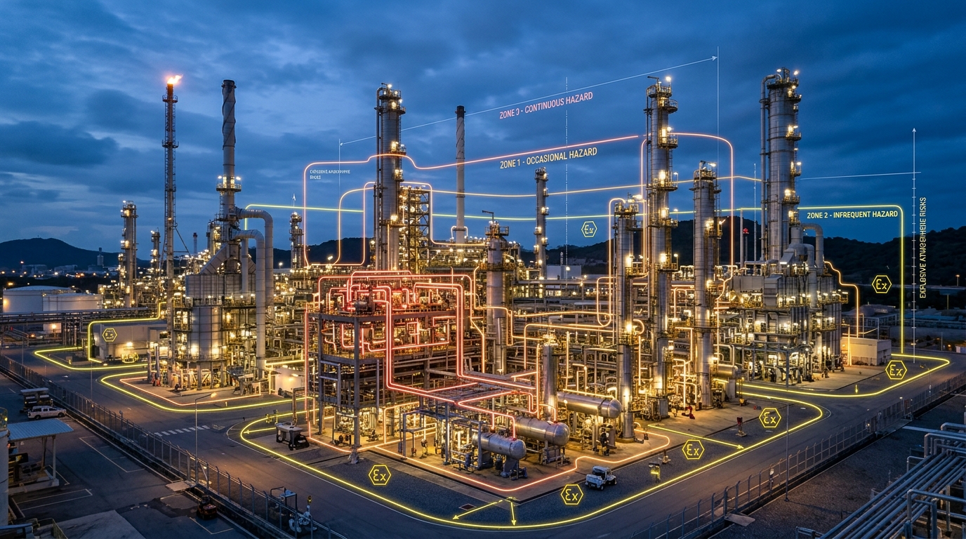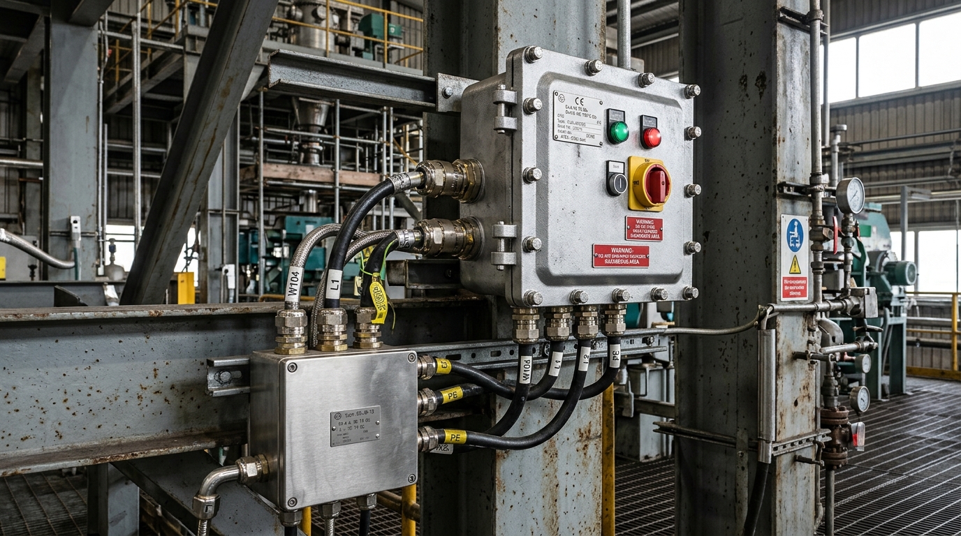
In industrial process plants operating in explosive atmospheres—such as crude oil refineries, petrochemical complexes, natural gas processing facilities, and offshore platforms—selecting the proper explosion protection concept is critical to both personnel safety and operational reliability. Two of the most widely deployed methods defined under the IEC 60079 series are Flameproof Enclosures (“Ex d”) and Increased Safety (“Ex e”). While both methodologies achieve compliance for Zone 1 and Zone 2 environments, their underlying protection philosophies, mechanical designs, and maintenance requirements represent fundamentally distinct engineering approaches.
1. The Combustion Physics: The Fire Triangle
An explosion in a hazardous area requires three components simultaneously: a combustible fuel (flammable gas, vapour, or mist), an oxidizer (atmospheric oxygen), and an ignition source (an electrical arc, electrostatic discharge, or high surface temperature). Standard industrial electrical equipment inevitably generates sparks during contact switching or develops hot surfaces during continuous operation.
To prevent electrical apparatus from igniting the surrounding hazardous environment, international explosion safety standards define two contrasting engineering philosophies:
- Containment (Ex d): Accept that explosive gas will enter the enclosure and ignite, but construct the enclosure to mechanically contain the explosion pressure and quench any escaping flames before they can ignite the external atmosphere.
- Prevention (Ex e): Prevent the formation of arcs, sparks, and excessive surface temperatures altogether through enhanced electrical insulation, robust ingress protection, and strict mechanical safety margins.
Core Standard References
IEC / EN 60079-1: Explosive atmospheres – Part 1: Equipment protection by flameproof enclosures “d”
IEC / EN 60079-7: Explosive atmospheres – Part 7: Equipment protection by increased safety “e”
2. Flameproof Enclosures (“Ex d”): The Containment Principle
The Flameproof protection concept (governed by IEC 60079-1) recognizes that completely gas-tight enclosures are impractical in heavy industrial environments over decades of thermal cycling. Therefore, the enclosure is intentionally designed to withstand an internal deflagration without rupturing or undergoing permanent plastic deformation.
Engineered Flame Paths & Maximum Experimental Safe Gap (MESG)
When an internal ignition occurs, expanding hot gases are forced to escape through tightly toleranced mechanical joints known as flame paths (flanged joints, spigot joints, or threaded paths). As hot gases pass through the flame path, heat is rapidly conducted away by the thick metal walls of the enclosure. By the time escaping gases emerge into the surrounding atmosphere, their temperature has cooled well below the auto-ignition temperature (AIT) of the external gas.
The critical dimension is the Maximum Experimental Safe Gap (MESG), which varies by Gas Group (Group IIA: MESG > 0.9 mm; Group IIB: 0.5 mm ≤ MESG ≤ 0.9 mm; Group IIC: MESG < 0.5 mm). This requires precision CNC machining, strict surface roughness standards (Ra ≤ 6.3 µm), and heavy cast aluminium or marine-grade stainless steel housings with substantial wall thickness.
Typical Ex d Applications
- Moulded case circuit breakers (MCCBs), motor contactors, and thermal overload relays.
- Variable Frequency Drives (VFDs) and high-power motor control centers (MCC).
- Heavy industrial control switches, pushbuttons with internal arcing contacts.
- Explosion-proof camera housings and CCTV pan-tilt surveillance systems.
3. Increased Safety (“Ex e”): The Prevention Principle
Unlike flameproof enclosures, Increased Safety (“Ex e”) equipment (IEC 60079-7) does not allow internal ignition to occur. Instead, it incorporates an elevated safety factor into every mechanical and electrical dimension to ensure that no arcs, sparks, or excessive temperatures can develop under both normal operation and specified abnormal conditions.
Key engineering features of Ex e apparatus include:
- Superior Ingress Protection: Minimum rating of IP54, with modern Maple industrial junction boxes achieving IP66/IP67 utilizing high-grade foamed silicone or neoprene gaskets.
- High Tracking Resistance Insulation: Use of high-grade moulding compounds with a Comparative Tracking Index (CTI ≥ 600 V) to eliminate surface dielectric breakdown.
- Generous Creepage and Clearance Distances: Significantly greater spacing between live conductor terminals compared to ordinary commercial equipment.
- Anti-Loosening Terminals: Spring-clamp or self-locking screw terminals designed to withstand severe plant vibration without loosening or generating micro-arcing.
4. The Modern Engineering Solution: The Hybrid “Ex de” Architecture
In modern chemical and oil refinery design, specifying massive Ex d cast enclosures for every control station results in severe weight penalties, difficult installations, and cumbersome maintenance. The optimal international engineering standard is the hybrid “Ex de” modular configuration.
Under this design philosophy:
- The sparking contacts (pushbutton contact blocks, rotary switches, indicator LEDs) are encapsulated in compact, factory-sealed flameproof (“Ex d”) modular sub-components.
- These Ex d modules are mounted inside a lightweight, highly corrosion-resistant glass-fibre reinforced polyester (GRP) or 316L stainless steel Increased Safety (“Ex e”) enclosure.
- The plant field wiring is terminated into Ex e spring-loaded terminals using standard Ex e cable glands—completely eliminating the need for expensive poured barrier glands or heavy conduit seals.
5. Engineering Selection Matrix: Ex d vs. Ex e
| Parameter | Flameproof (“Ex d”) | Increased Safety (“Ex e”) |
|---|---|---|
| Governing Standard | IEC / EN 60079-1 | IEC / EN 60079-7 |
| Core Principle | Containment & flame quenching | Prevention of sparks & hot spots |
| Permissible Components | Arcing, sparking, high-power gear | Non-sparking terminals, certified LEDs |
| Enclosure Weight | Heavy (thick cast alloy/steel) | Lightweight (GRP or 1.5mm SS316L) |
| Cable Entry Glands | Ex d barrier gland / compound seal | Standard Ex e compression gland |
| Maintenance Demands | High: check flame path gaps & torques | Low: visual gasket & terminal check |
6. Conclusion & Engineering Consultation
In summary, neither concept is universally superior; their deployment is dictated by the specific equipment function. High-voltage switchgear, circuit breakers, and heavy power components require the robust containment of Ex d, while terminal enclosures, junction boxes, and lighting distribution systems achieve maximum cost-efficiency, corrosion immunity, and ease of installation with Ex e or Ex de.
Maple Pakistan (Pvt.) Ltd. provides turnkey engineering support, customized Ex de control stations, and ATEX/IECEx certified solutions tailored to the exacting requirements of Pakistan’s chemical, fertilizer, and petrochemical industries. Contact our technical engineering team in Karachi, Lahore, or Islamabad for custom application appraisals.