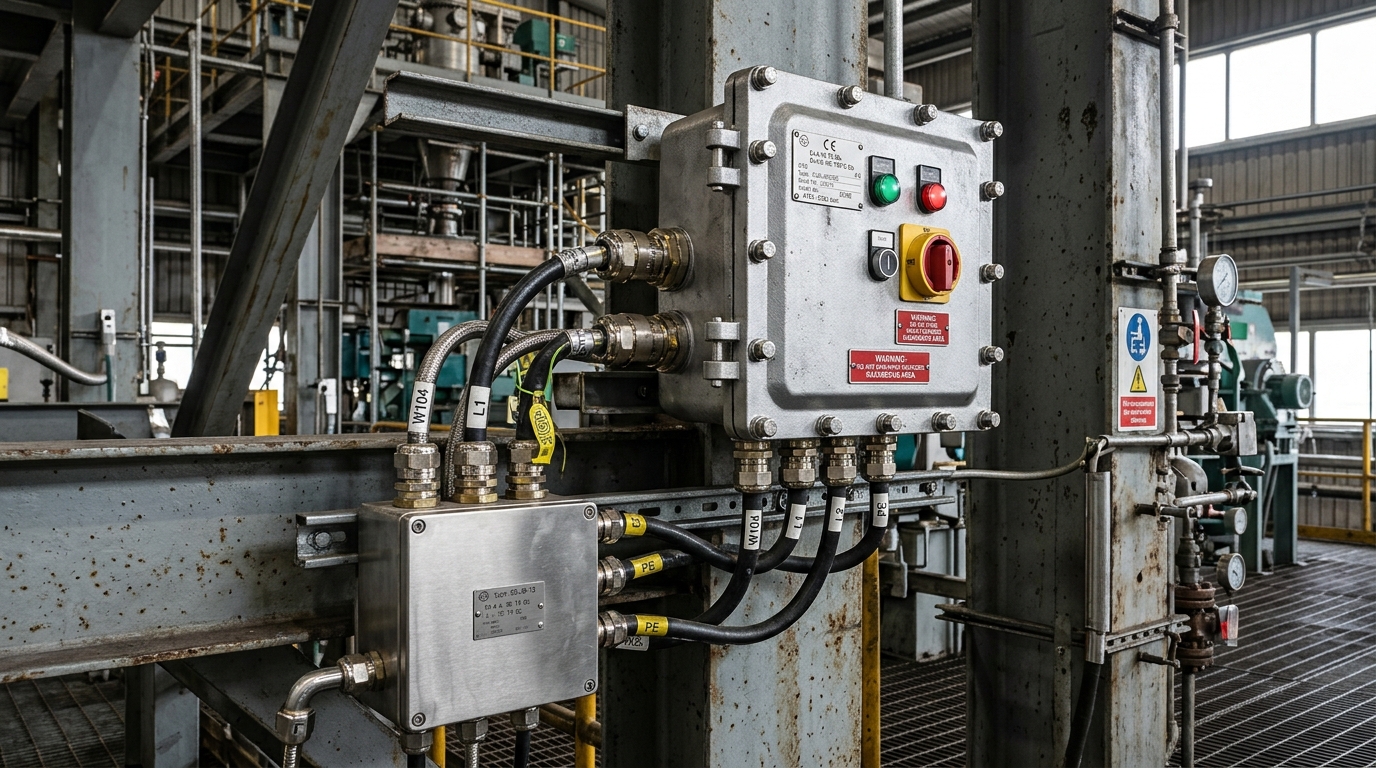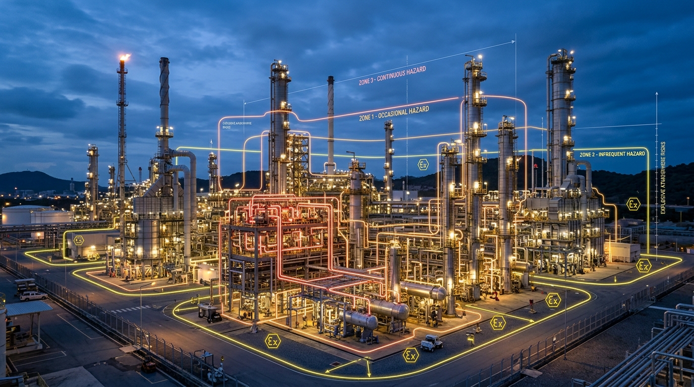
Among the diverse explosion protection techniques established under international standards, Intrinsic Safety (protection concept “Ex i”) stands alone as the only technology certified for use in Zone 0 hazardous locations, where explosive gas atmospheres are present continuously or for extensive operating periods. Governed by IEC / EN 60079-11, Intrinsic Safety approaches the ignition problem from an energy-limitation perspective rather than containment or mechanical isolation.
1. The Fundamentals of Energy Limitation
Every combustible gas-air mixture requires a finite minimum threshold of thermal and electrical energy to initiate combustion, known as the Minimum Ignition Energy (MIE). Representative values demonstrate the sensitivity of industrial gas groups:
- Gas Group IIA (Propane): MIE ≈ 180 µJ
- Gas Group IIB (Ethylene): MIE ≈ 60 µJ
- Gas Group IIC (Hydrogen): MIE ≈ 20 µJ (Extremely sensitive)
The fundamental principle of Intrinsic Safety is to design the entire electrical measurement loop such that the maximum electrical energy stored in capacitive ($E = frac{1}{2} C V^2$) or inductive ($E = frac{1}{2} L I^2$) components remains below the threshold required to ignite the surrounding atmosphere—even in the event of component failures, short circuits, or wiring faults.
2. Levels of Protection: Ex ia, Ex ib, and Ex ic
IEC 60079-11 subdivides the Intrinsic Safety concept into three distinct protection levels based on fault tolerance and safety factors:
| Protection Level | Permitted Faults | Safety Factor | Permitted Zones |
|---|---|---|---|
| Ex ia | Safe with TWO independent countable faults | 1.5 × safety factor | Zone 0, Zone 1, Zone 2 |
| Ex ib | Safe with ONE countable fault | 1.5 × safety factor | Zone 1, Zone 2 |
| Ex ic | Safe under normal operation (0 faults) | 1.0 × safety factor | Zone 2 only |
3. Components of an Intrinsically Safe System
An intrinsically safe circuit is evaluated as a complete interconnected system comprising three fundamental elements:
- Field Apparatus: Located in the hazardous area. This can be either Simple Apparatus (passive components storing negligible energy, such as RTDs, thermocouples, potential-free contact switches, and LEDs requiring no certificate) or Certified IS Apparatus (transmitters, I/P converters, solenoid valves with entity parameters).
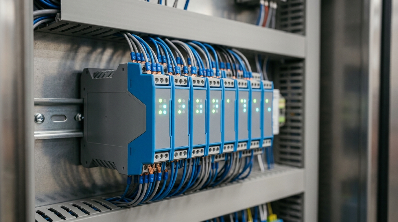
- Associated Apparatus (Barriers/Isolators): Installed in the non-hazardous safe area (or inside an Ex d/p enclosure). It restricts the voltage and current delivered to the field loop.
- Interconnecting Field Cabling: Distributed capacitance ($C_c$) and distributed inductance ($L_c$) across long cable runs must be accounted for during loop calculations.
4. Zener Barriers vs. Galvanic Isolators
When interfacing safe-area control systems (DCS / PLC) with hazardous area sensors, engineers must choose between two primary barrier technologies:
Zener Diode Safety Barriers
Passive networks consisting of precision Zener diodes (voltage clamping), current-limiting resistors, and fast-acting fuses.
- Low hardware cost and ultra-compact DIN-rail footprint.
- Critical Requirement: Must be connected to a dedicated, high-integrity Ex clean earth with an electrical resistance under 1 Ohm.
- Susceptible to ground potential loops and plant electromagnetic noise.
Galvanic Isolators
Active electronic modules utilizing isolation transformers and optical couplers to physically segregate the safe-area and hazardous-area circuits.
- No dedicated Ex earthing system required; eliminates earth ground loops completely.
- Provides built-in signal conditioning, line-fault detection, and HART pass-through.
- Industry standard for offshore platforms, large refineries, and greenfield automation.
5. Entity Concept Verification: The Golden Rules
Under the IEC 60079-14 installation standard, engineers must verify loop compliance by comparing the output parameters of the barrier/associated apparatus against the input parameters of the field sensor and the cable:
• Maximum Current: Io ≤ Ii
• Maximum Power: Po ≤ Pi
• Allowable Capacitance: Co ≥ Ci + C_cable
• Allowable Inductance: Lo ≥ Li + L_cable
6. Field Installation Best Practices in Pakistan
To maintain system integrity throughout the lifecycle of the plant:
- Light Blue Sheathing: All intrinsically safe signal cables must be identified by distinctive light-blue sheathing or prominent blue terminal tags.
- Physical Segregation: Maintain a minimum physical clearance of 50 mm between IS and non-IS conductors in marshalling cabinets, or use grounded metal dividing partitions.
- Cable Shielding: Use individually screened twisted pairs grounded at one point only (typically at the control cabinet) to prevent induced circulating currents.
Maple Pakistan’s automation and instrumentation specialists assist engineering procurement teams with comprehensive entity loop calculations, SIL-rated galvanic isolator supply, and compliance audits for process automation across Pakistan.